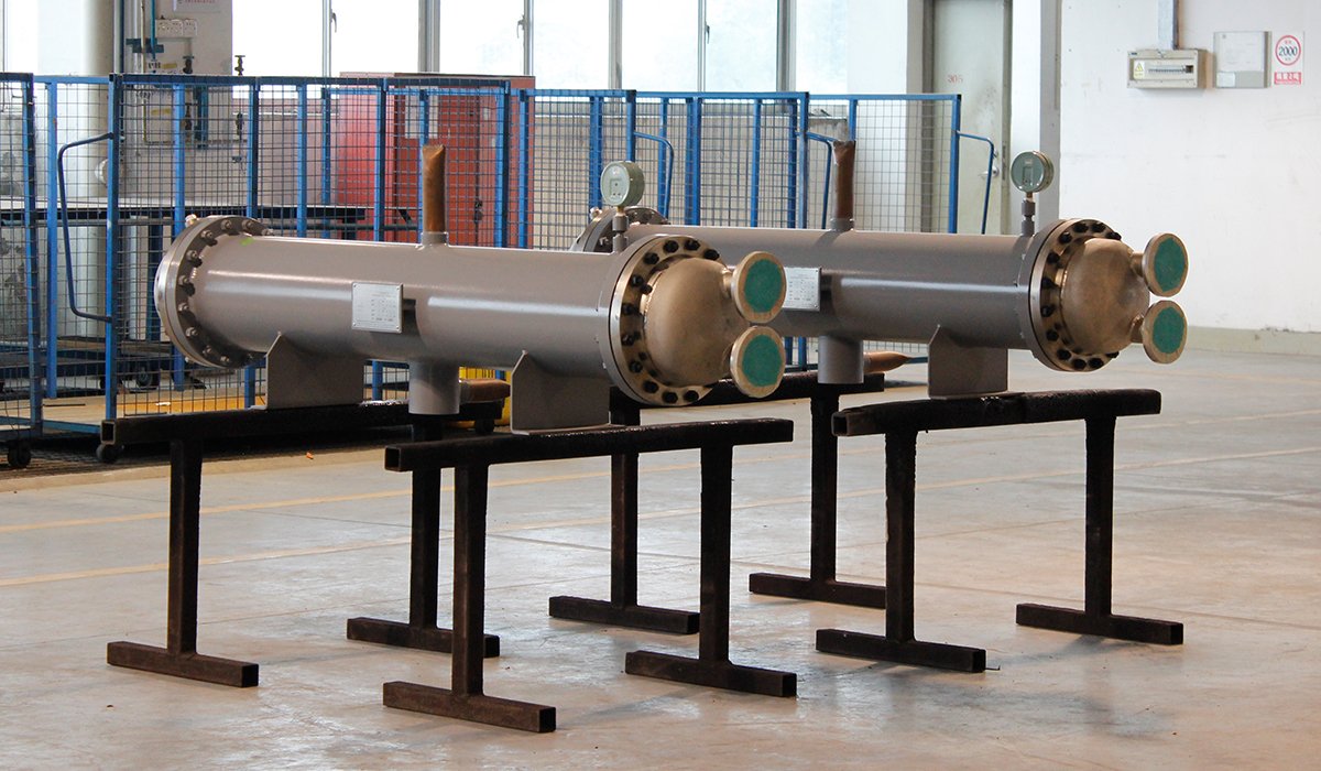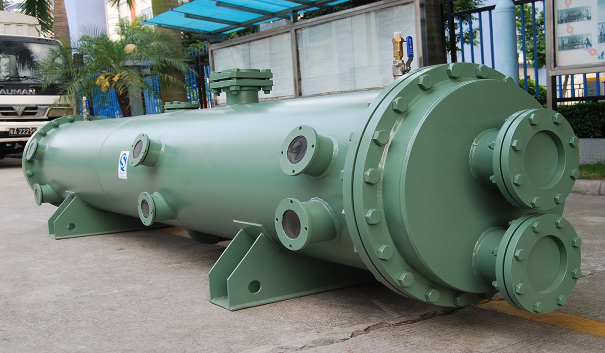
The basic principle of a shell and tube heat exchanger is simple, yet what truly determines its performance is the engineering design underlying that simplicity. This article begins with the fundamental process of heat transfer, progressively breaks down the internal operation of shell-and-tube heat exchangers, and further explains the factors that influence equipment performance.
What Is a Shell and Tube Heat Exchanger?
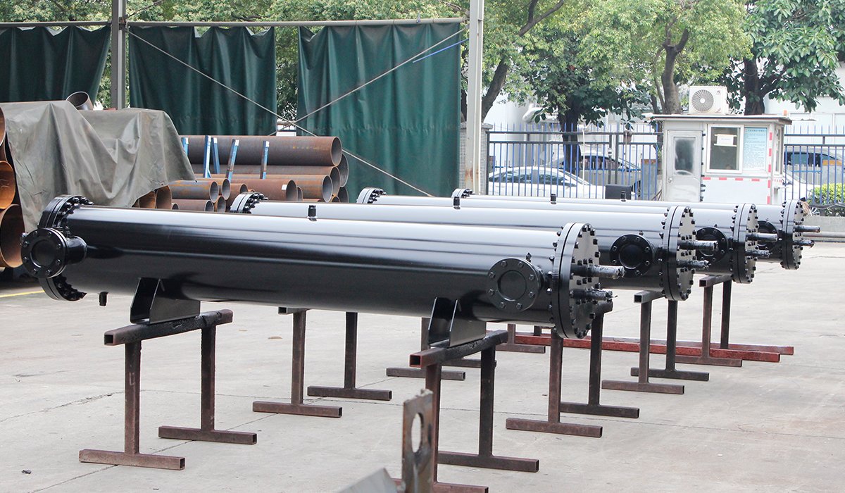
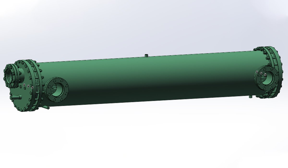
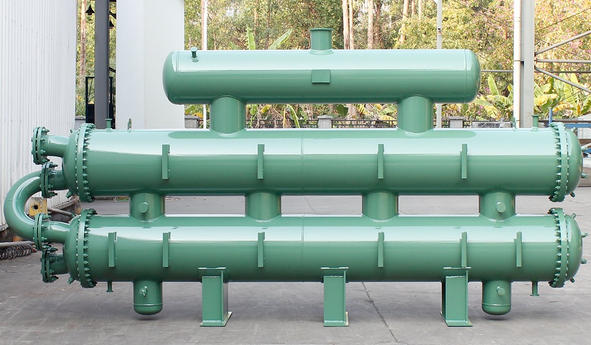
A shell and tube heat exchanger is a type of pressure vessel containing a number of tubes.One fluid flows through the tubes — that’s the tube side. The other fluid flows in the space between the tubes and the vessel wall — that’s the shell side. The tube wall separates them, and heat crosses that wall from the hotter fluid to the colder one. In the drawings, we can see that the main components include the shell, tube, tubesheet, baffles, heads/channels, and nozzles.
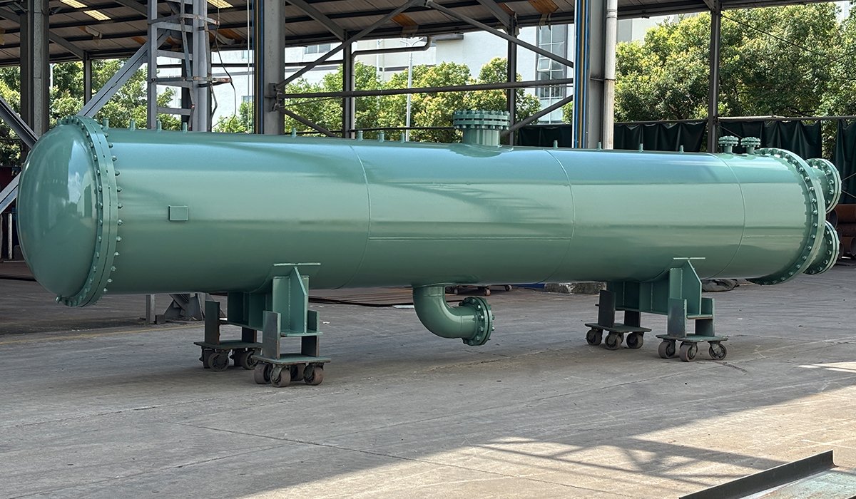
| Part | What it does | What we watch on the shop floor |
| Shell | The outer cylinder. Holds the shell-side fluid and the pressure. | Carbon steel is normal. Stainless or Cu-Ni when the fluid is seawater or anything mean. |
| Tubes | The heat transfer surface. This is where the money is. | 19 mm (3/4″) OD is the workhorse. 25 mm (1″) when the fluid is filthy and needs mechanical cleaning. |
| Tube sheets | Thick plates that grip every tube end and keep the two fluids apart. | Tubes are rolled in, welded, or both. A leaking tube joint is the number one warranty call in this industry, and it almost always traces to a bad expansion or a dirty weld groove. |
| Baffles | Plates that force shell-side fluid across the tubes instead of letting it slip past. | Segmental baffles with a cut of 20–25% of the shell diameter is the classic. More cut means less pressure drop but sloppier flow. There’s a right answer for your fluid, and it’s not “whatever is lying around.” |
| Heads (channels) | End boxes that feed fluid into the tubes and collect it on the way out. | Partition plates inside split the flow into multiple passes. A bolted head with a gasket means you can open it and clean it. |
| Nozzles | Inlet and outlet connections for both sides. | Sized for velocity, not just pipe convenience. Undersized nozzles are a quiet performance killer. |
| Expansion provision | Something that absorbs the difference in thermal growth between shell and tubes — a U-tube bundle, a floating head, or an expansion joint in the shell. | Skip this on a fixed-tubesheet unit with a big temperature difference and the tubesheet will eventually crack. We’ve seen it. It’s not a fun phone call. |
How Does a Shell and Tube Heat Exchanger Work?
The working principle of a shell and tube heat exchanger can be simply understood as allowing two fluids at different temperatures to exchange heat without directly mixing.The basic process can be understood in four steps.
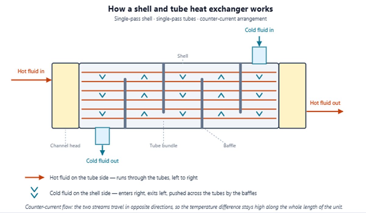
Hot and Cold Fluids Enter Their Respective Flow Channels
Depending on the application, the hot fluid may flow through the tubes while the cold fluid flows through the shell side—or the arrangement may be reversed.
The choice of tube side and shell side is not arbitrary. Fluid pressure, temperature, flow rate, viscosity, fouling tendency, corrosion, cleaning requirements, and allowable pressure drop all need to be considered during design. Arbitrarily deciding the shell-side and tube-side arrangements can lead to equipment incompatibility or a shortened service life.
Heat Is Transferred Through the Tube Walls
The heat transfer process involves three stages:
Hot fluid → convection → tube wall → conduction → convection → cold fluid
For example, if hot water flows through the tubes and cold water flows around them:
Heat moves from the hot water to the inner surface of the tube.
Heat conducts through the metal tube wall.
Heat moves from the outer tube wall into the cold water.
The hot water cools down while the cold water heats up.
The tube wall acts as a physical barrier. This allows heat to be transferred while keeping the two fluids separated. The tube material therefore matters. You should select materials such as carbon steel, stainless steel, copper alloys, or titanium based on thermal conductivity, corrosion resistance, temperature, pressure, fluid chemical properties, and operating conditions.
Baffles Control the Flow of the Shell-side Fluid
The shell-side fluid does not simply enter the shell and move straight from the inlet to the outlet. In many shell and tube heat exchangers, baffles are installed inside the shell to redirect the shell-side fluid across the tube bundle.
This creates a longer and more controlled flow path and can increase fluid velocity and turbulence around the tubes.Better flow conditions can improve the shell-side heat transfer coefficient and therefore improve overall heat transfer performance.
When customizing the design, you must comprehensively consider factors such as baffle spacing, baffle cut height, shell diameter, fluid velocity, and pressure drop. Do not arbitrarily increase the number of baffles or intensify turbulence, as more intense is not always better. These changes could potentially lead to an increase in the pressure drop across your heat exchanger, thereby affecting its performance.
The Heated or Cooled Fluids Exit the Heat Exchanger
Eventually, the hot fluid leaves at a lower temperature.And the cold fluid leaves at a higher temperature. The fluids remain separated, but their temperatures change according to the required heat duty and the design of the exchanger. The actual outlet temperatures depend on several factors, including flow rate, inlet temperatures, fluid properties, heat transfer area, overall heat transfer coefficient, flow arrangement, and fouling condition. Therefore, before the design phase, you need to inform the manufacturer of all potentially influential factors. This ensures that the actual outlet temperature meets your project’s requirements.
Shell Side vs. Tube Side: Which Fluid Goes Where?
In a shell and tube heat exchanger, either fluid can usually be placed on the tube side or shell side. The right choice depends on your actual operating conditions. And this choice matters. It affects heat transfer, pressure drop, material selection, cleaning, fouling, equipment cost, and service life.
Tube-side flow is easier to control and, in many designs, easier to clean mechanically. The shell-side fluid flows around the tube bundle. Baffles are commonly used to redirect this flow across the tubes. This is important because the shell-side flow path strongly affects heat transfer. If the shell-side fluid moves too slowly, heat transfer may be poor. If you force the fluid to move too fast, pressure drop can become excessive and tube vibration or erosion may become a concern.
However, depending on the heat exchanger’s design, cleaning the shell side may prove quite difficult. Therefore, for your project, it is not recommended to place fluids prone to fouling on the shell side; this helps avoid unnecessary maintenance issues later on.
Which fluid goes where? There is no specific standard. The following issues should be considered based on the specific fluid:
Pressure
Is the Fluid Corrosive
Does the Fluid Foul Easily
How Much Pressure Drop Can You Allow
Flow Rates
What Happens If the Fluid Changes Phase
When choosing a flow path, you are not deciding between two options that are simply “good” or “bad.” Once these conditions are clarified, you can determine which fluid should flow through the tubes and which through the shell. If someone tells you to “feed the hot fluid into the tube side” without asking about the operating conditions, you should be wary.
Your goal should not merely be to determine the direction of fluid flow, but to design a flow arrangement that meets heat transfer requirements while avoiding unnecessary pressure drop, fouling, corrosion, or maintenance issues.
| Your fluid | Put it on | Why |
| Dirty, scaling, or fouling | Tube side | You can rod or hydroblast a tube. Cleaning the inside of a baffled shell is a nightmare nobody wants. |
| Corrosive | Tube side | You only need exotic alloy for the tubes and channel. The big shell can stay carbon steel and save you a fortune. |
| High pressure | Tube side | A small tube handles internal pressure cheaply. A large shell under the same pressure needs a much thicker wall — weight and cost go up fast. |
| Clean condensing steam or vapor | Shell side | Condensation doesn’t need high velocity, and the shell gives condensate room to drain away. |
| Viscous fluid, like heavy oil | Shell side | Baffle-driven cross flow helps thick fluids far more than anything you can do inside a tube. |
Why Do Baffles Matter in a Shell and Tube Heat Exchanger?
If you look inside a shell and tube heat exchanger, you will see a series of plates installed across the shell. These are called baffles. Baffles do three jobs:
They create cross flow and turbulence.
This is the big one. Fluid sitting against a tube wall forms a thin stagnant layer — the boundary layer — and it acts like insulation. Sweeping fluid across the tubes at an angle breaks that layer up repeatedly. Shell-side heat transfer coefficients can improve several-fold compared with an unbaffled straight-through flow.
They support the tubes.
A tube bundle is a few hundred thin tubes several meters long. Without support plates, those tubes sag, and moving fluid makes them vibrate. Vibration is how tubes wear through at the baffle holes — one of the most common failures we see in units that were “cheap” and “high performance” on paper.
They shape your pressure drop.
Push fluid across the bundle more aggressively and heat transfer goes up, but so does pressure drop. There’s a trade-off here, and the split has to be decided per application.
But more baffles are not always better.You might think that adding more baffles will always improve heat transfer. In reality, it is a trade-off. More baffles or smaller baffle spacing can increase fluid velocity and turbulence. But they can also increase pressure drop. If the pressure drop becomes too high, your pump needs more energy to maintain the required flow. So you need to balance.
Counterflow And Parallel Flow
Two fluids, two directions. Same machine. Very different results.
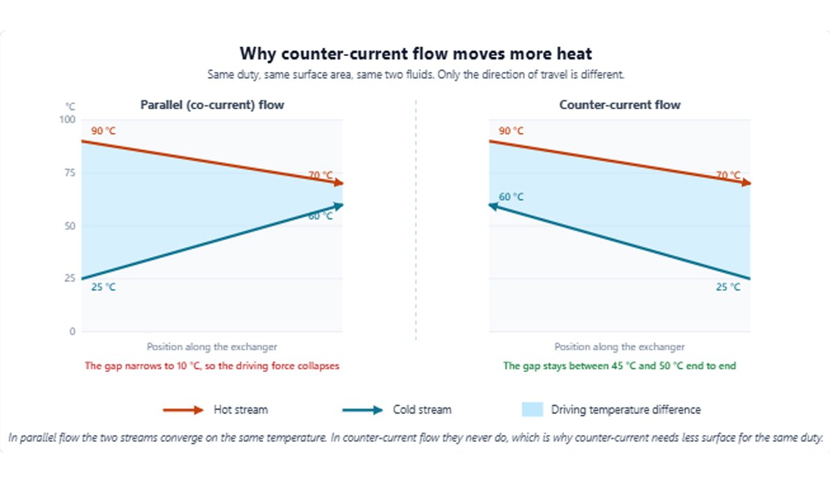
Parallel flow occurs when two fluids enter from the same end and flow in the same direction. You get a huge temperature difference at the inlet — great heat transfer for a few inches — then the two fluids converge toward the same temperature and the driving force collapses. The cold fluid can never leave hotter than the hot fluid leaves. Physics won’t let you. Counterflow involves fluid entering from both ends. The coolest water meets the coolest oil at one end. The warmest water meets the hottest oil at the other. The temperature gap stays alive the whole way through.Because the temperature profiles are more favorable, counterflow can often achieve a higher heat transfer effectiveness than parallel flow for the same heat transfer area.
In many heat exchanger applications, counterflow provides a better temperature profile and can achieve a higher heat transfer effectiveness. But that does not mean counterflow is automatically the right choice for every application. Parallel flow can also perform well under specific temperature or design constraints.
In a real shell and tube heat exchanger, the flow is often more complicated than a simple two-stream diagram. Multiple tube passes, shell passes, baffles, crossflow, and phase changes can all affect the actual temperature distribution. That’s why engineers often use the LMTD correction factor when calculating the required heat transfer area for multipass heat exchangers.
How to Select a Shell and Tube Heat Exchanger?
Selection is not a matter of taste. It’s a short list of decisions, in order:
Nail your duty.
Heat load, flow rates, and all four temperatures. Without these, nobody can size anything.
Decide fluid placement.
Dirty, corrosive, and high-pressure fluids go tube side. Condensing vapor and viscous fluids usually go shell side. Note any conflicts and flag them for your supplier.
Pick the construction.
Fixed tubesheet for modest temperature differences and clean service. U-tube when thermal expansion is large and the tube side is clean. Floating head when the fluid fouls and you can’t afford downtime.
Choose materials honestly.
Carbon steel for benign service. Stainless where corrosion is mild. Cu-Ni or titanium for seawater. Give real chemistry data.
Check the pressure drop budget.
Tell the supplier what your pumps can handle. Ask them to confirm the design fits.
Confirm cleaning, access, and standards.
Can you remove the head? Can you pull the bundle? ASME VIII Div. 1? PED 2014/68/EU? Local code? Sort that out before the drawing is frozen, not after.
Confirming the information above will help you select the most suitable equipment more quickly. Incorrect information can lead to errors in equipment selection. The immediate consequence could be a delay in your project schedule; in a worst-case scenario, the purchased heat exchanger might prove unusable. Therefore, providing accurate information is essential.
FAQ
Can the two fluids ever mix?
Not by design. The tube walls are the barrier. If they’re mixing, a tube has failed or a tubesheet joint has leaked, and it’s time to isolate, test, and plug or replace.
Should the hot fluid always go on the shell side?
No. Temperature is not the deciding factor. Fouling, corrosion, pressure, viscosity, and phase change are. A hot, dirty fluid still belongs in the tubes; a cool, clean condensing vapor still belongs in the shell.
How do I know if my exchanger is underperforming?
Compare your actual outlet temperatures and pressure drops with the datasheet at current flow rates. Falling short on temperature usually means fouling or lost area. Pressure drop climbing above design usually means blocked tubes or deposits on the shell side.
What Actually Determines Heat Exchanger Performance?
Heat transfer area, fluid velocity, temperature difference, flow arrangement, baffle design, tube passes, fluid properties, fouling, material selection.
Why is tube vibration a concern in shell and tube heat exchangers?
High shell-side flow velocity and inappropriate baffle spacing can cause tubes to vibrate. Repeated vibration can lead to wear at the baffle holes, tube fatigue, and eventually tube failure. A vibration check should be part of the mechanical design, particularly for high-flow or large shell-side applications.
Does a larger heat exchanger always provide better performance?
No. Increasing heat-transfer area does not automatically make an exchanger a better design. An oversized exchanger can increase equipment cost, footprint, material consumption, and sometimes pressure drop without providing meaningful benefits. The exchanger should be sized according to the required duty, flow rates, temperatures, pressure drop, fouling conditions, and operating margin.
How should I compare two shell and tube heat exchanger quotations?
Do not compare quotations based only on price or heat-transfer area. Check the technical datasheet, including tube diameter and length, tube count, tube material, shell diameter, baffle arrangement, baffle spacing, design pressure, design temperature, heat-transfer coefficient, pressure drop, fouling allowance, and applicable standards. Two exchangers with the same heat-transfer area can have significantly different designs and costs.
Request a Custom Shell and Tube Heat Exchanger
Send UAR your duty. Fluids, flows, temperatures, pressures, and the pressure drop you can afford — eight lines, listed above.
Our engineers will work through side placement, construction type, baffle layout, and materials, then come back with a thermal datasheet you can hold against any other quote. If your numbers have a problem — an impossible temperature approach, a ΔP that won’t work — we’ll tell you that too, before you spend anything. No script. No brochure talk. Just the design. Send us a quote now.