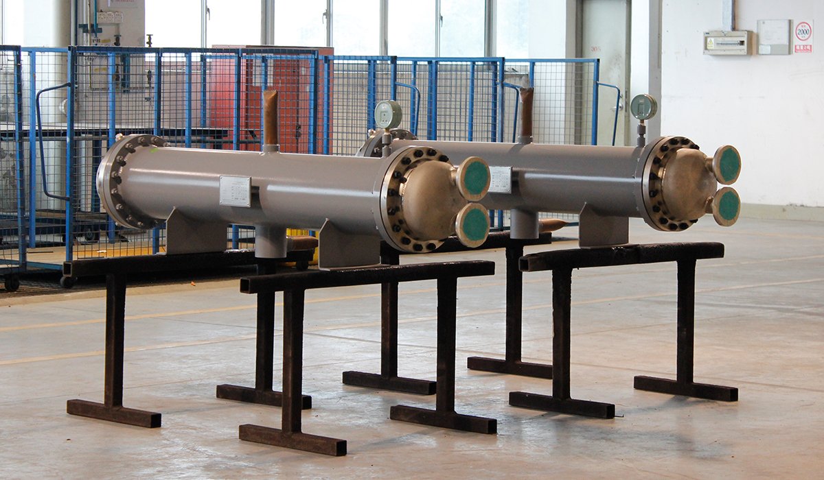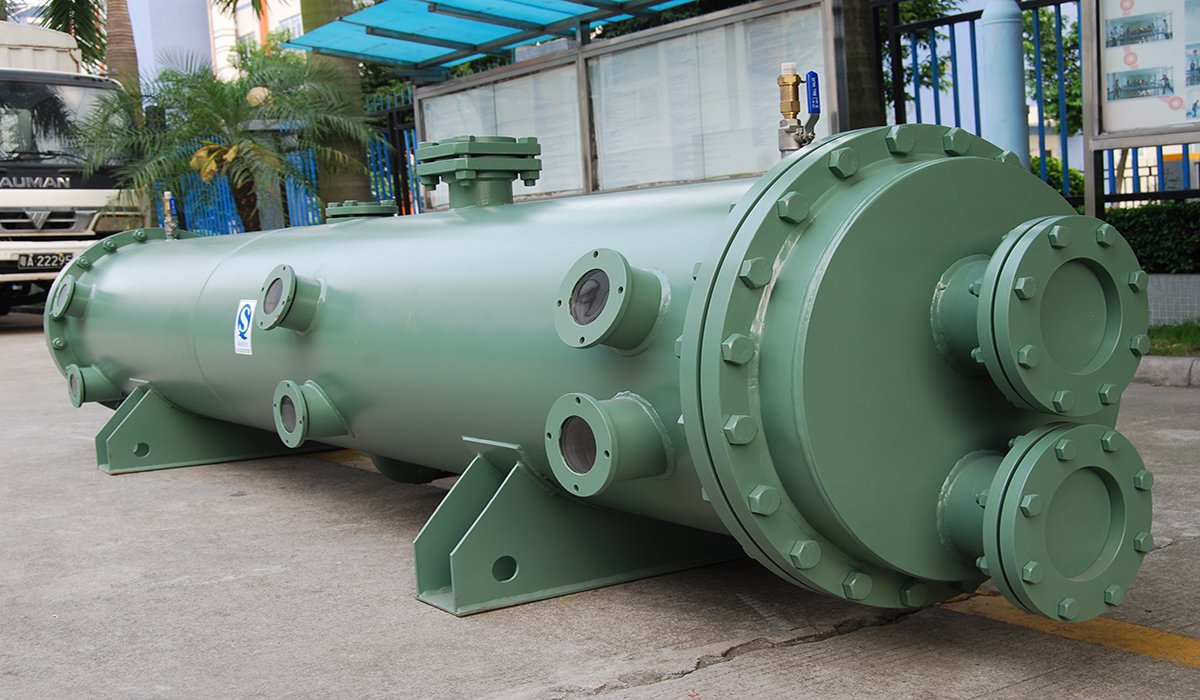
As a high-efficiency variant of shell and tube evaporators, the design of a falling-film evaporator involves far more than merely calculating the required heat transfer area. The final design must strike a precise balance among thermal load, liquid distribution and film formation, pressure drop and flow velocity, fouling tendency, material compatibility, mechanical strength, and maintenance requirements.
What is a Falling-film Evaporator
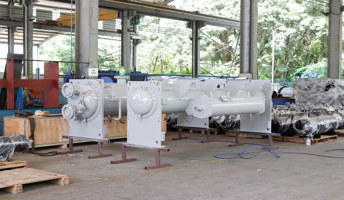
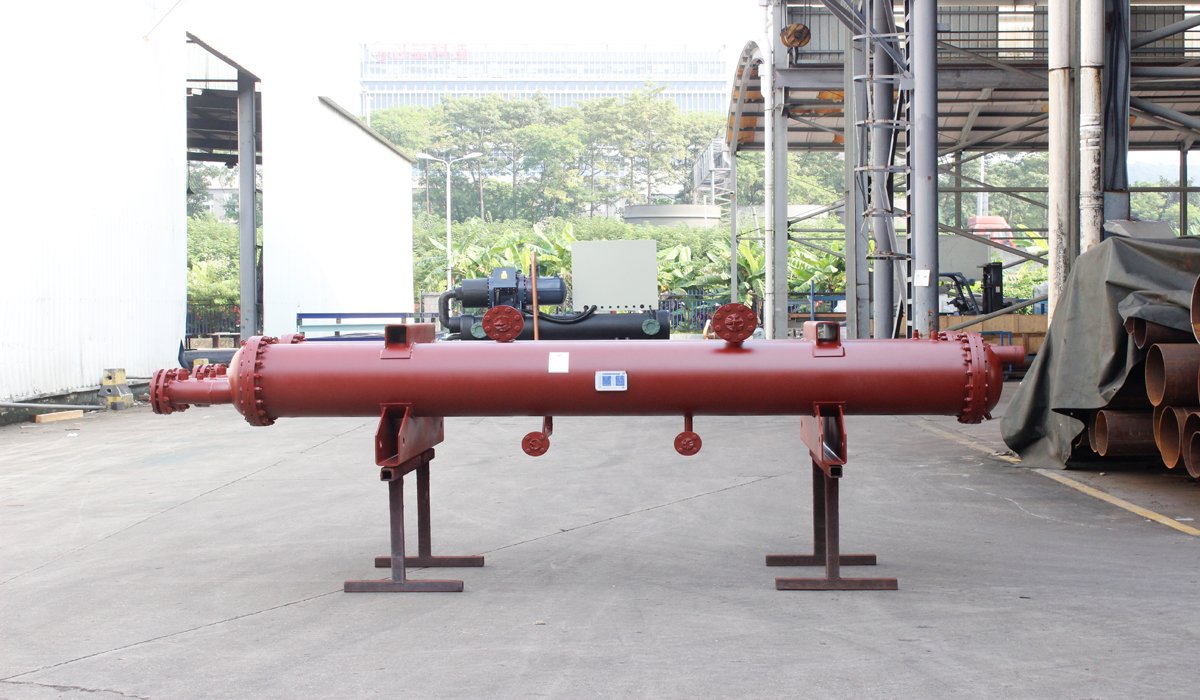
A falling-film evaporator is a type of shell-and-tube evaporator that achieves efficient heat exchange through the evaporation of a liquid film. Its operating principle is as follows: liquid refrigerant is evenly distributed by a device at the top and flows downward along the inner walls of the heat exchange tubes, forming a uniform, thin liquid film. As the film flows, it absorbs heat from the medium outside the tubes and evaporates, thereby facilitating heat transfer and cooling.
Compared to other types of evaporators—such as flooded or dry-expansion models—falling-film evaporators offer advantages such as a lower refrigerant charge, higher heat exchange efficiency, lower energy consumption, and the formation of a uniform, stable liquid film. If you have high energy efficiency requirements, such as for use in large-scale high-efficiency chillers, data center cooling, industrial process refrigeration, etc., it is a core heat exchange component that is increasingly widely used in medium and large-scale refrigeration systems.
Information Required for Designing a Falling Film Evaporator
Processing Capacity
You need to specify the required heat load for the evaporator, as well as the mass and volumetric flow rates of the media involved. This information forms the basis for determining the overall specifications, the number and arrangement of heat exchange tubes, and directly influences the equipment’s heat transfer capacity and physical dimensions.
Fluid / Refrigerant Characteristics
The physicochemical properties of the media directly affect heat transfer coefficients, fouling tendencies, liquid distribution design, and material selection. For instance, if your project involves seawater or corrosive process fluids, specific material and structural designs will be required.
Therefore, you need to identify the media types for both sides of the heat exchanger: the tube side typically carries a heat transfer fluid (such as water or glycol solution), while the shell side contains the refrigerant (such as R134a, R410a, or R1234ze); industrial applications may also involve specialized process fluids.
Temperature and Pressure
You need to provide inlet and outlet temperatures for both the hot and cold sides, the evaporation temperature, and the operating and design pressures for both the shell and tube sides.
Temperature parameters determine the heat transfer driving force and the Logarithmic Mean Temperature Difference (LMTD), serving as the core basis for calculating heat transfer area. Falling film evaporators have strict requirements regarding the uniformity of evaporation temperature; parameter accuracy directly impacts film formation quality and operational stability.
Material Requirements
You may specify material requirements based on media corrosiveness and industry hygiene standards for the food or pharmaceutical sectors. The choice of materials for heat exchange tubes, the shell, and liquid distribution components determines not only corrosion resistance and service life but also heat transfer performance and the project’s overall cost.
Project Requirements
In addition to basic process parameters, you need to define specific requirements based on actual operating conditions. These include installation space constraints, maintenance needs, applicable industry standards and certifications ,such as PED, ASME, or classification society certifications, and special requirements for unique applications like marine use, offshore platforms, or cleanrooms. These factors will ultimately influence the equipment’s structural design and configuration.
Recommended Design Workflow for Falling Film Evaporators
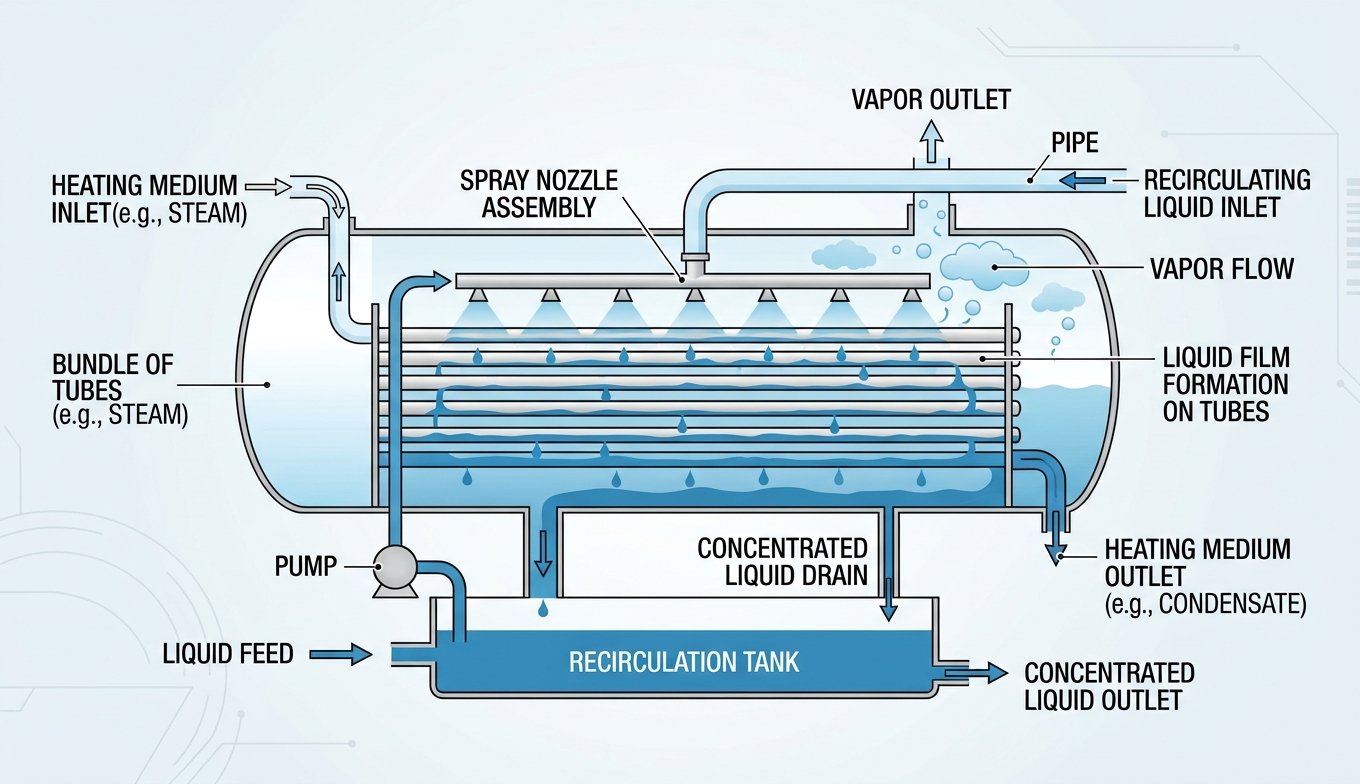
The design process for a falling film evaporator begins with your specific process conditions and thermal load requirements. Following preliminary heat transfer calculations, the focus shifts to optimizing liquid distribution and the tube bundle—specifically addressing the unique characteristics of falling film evaporation—before concluding with a comprehensive performance verification. The standard design workflow is as follows:
Confirm process parameters → Calculate thermal load → Calculate Logarithmic Mean Temperature Difference (LMTD) → Estimate overall heat transfer coefficient
↓
Calculate required heat transfer area → Design heat transfer tube bundle → Design liquid distribution system → Design shell and structural components
↓
Verify tube-side/shell-side pressure drop → Select materials and design for mechanical strength → Check for thermal expansion and vibration
↓
Verify film formation uniformity → Final verification of overall performance
Within this process, the design of the liquid distribution system and the verification of film formation are the steps that distinguish falling film evaporators from conventional shell-and-tube evaporators; they are also critical to ensuring the equipment operates efficiently.
How to Design a Falling-Film Heat Exchanger Tube Bundle
The tube bundle is the core heat-transfer component of a falling-film evaporator; its design directly determines the equipment’s heat-transfer efficiency and the quality of the liquid film. Key considerations include:
Selection of Tube Diameter and Length
Falling-film evaporators require high uniformity in the internal liquid film; tube diameter selection must balance medium flow rate and the target film thickness. Excessively large diameters can lead to uneven film distribution, while diameters that are too small result in high flow resistance. Tube length must balance heat-transfer area requirements, installation space, and liquid distribution uniformity—excessive length risks film dry-out at the tube bottom, while insufficient length fails to fully utilize heat-transfer potential.
Design of Tube Count and Passes
The number of tubes can be preliminarily determined based on total and single-tube heat-transfer areas, followed by adjustments to the bundle layout to meet shell-side flow velocity requirements. Falling-film evaporators typically employ a single-pass design to ensure stable, top-to-bottom flow and avoid the disruptions to film continuity caused by multi-pass configurations.
Tube Bundle Layout
Layouts can be arranged in an equilateral triangular or square pattern. An optimal tube pitch ensures uniform shell-side fluid distribution and enhances overall heat-transfer efficiency, while also providing sufficient space for future cleaning and maintenance and balancing shell diameter for cost-effectiveness.
Why Are Liquid Distribution and Wetting Important
Liquid distribution and tube-wall wetting are core design elements of falling-film evaporators and prerequisites for efficient equipment operation. Their importance is evident in three key areas.
Determining the Upper Limit of Heat Transfer Efficiency
A uniform, thin liquid film maximizes the utilization of the heat transfer tube surface area, achieving exceptionally high heat transfer coefficients. Uneven distribution—resulting in dry spots on some parts of the tube wall and excessively thick films on others—significantly increases thermal resistance, thereby substantially degrading overall heat transfer performance.
Ensuring Operational Stability
Localized dry spots caused by uneven distribution can lead to overheating; prolonged operation accelerates material aging and may even cause equipment deformation or leaks. Furthermore, uneven film distribution causes fluctuations in evaporation, leading to vibration and noise that compromise the stability of the entire system.
Reduce scaling and maintenance costs
Complete wetting of the tube wall reduces the deposition of dirt on the tube wall and slows down the scaling rate; conversely, dry spots are prone to rapid scaling, which further deteriorates the heat exchange effect and increases your cleaning frequency and maintenance costs.
For these reasons, falling-film evaporators incorporate specialized components—such as liquid distributors and distribution trays—that utilize multi-stage flow splitting to ensure liquid is evenly distributed to every heat transfer tube. By optimizing the liquid distribution design, UAR falling-film evaporators achieve uniform wetting across the entire tube length, fully guaranteeing both heat transfer efficiency and operational stability.
Pressure Drop and Fouling
Pressure Drop Design
Falling-film evaporators rely on gravity to form the liquid film; consequently, overall flow velocities are relatively low, and pressure drops are generally lower than those of other evaporator types. Nevertheless, precise verification remains essential. Excessive tube-side pressure drop increases the energy consumption of feed pumps, while abnormal shell-side pressure drop often indicates uneven liquid distribution or suboptimal tube bundle layout. The primary design objective is to maintain both tube-side and shell-side pressure drops within permissible limits—balancing heat transfer performance against system energy consumption—while ensuring high-quality film formation and efficient heat transfer.
Fouling Prevention and Control
Fouling increases thermal resistance at the tube wall and reduces heat transfer efficiency; it also constricts flow passages and raises pressure drop, making it a critical factor affecting the evaporator’s long-term performance. The tendency for fouling in falling-film evaporators is closely linked to fluid properties, flow velocity, and the quality of film formation. The design can mitigate scaling by optimizing the medium flow rate, selecting scale-resistant materials, and ensuring full pipe wall wetting. The structure also features a detachable end cap design with pre-installed cleaning interfaces, facilitating mechanical or chemical cleaning later and extending the equipment’s lifespan.
FAQ
How is the size/specification of a falling film evaporator determined?
You can determine the specifications by using the thermal load as the primary basis, while also considering parameters such as medium flow rate, inlet and outlet temperatures, operating pressure, allowable pressure drop, medium properties, and fouling factors.
How is the heat transfer area of a falling film evaporator calculated?
The calculation of heat transfer area is based on the fundamental heat transfer equation:A=Q/UΔTF
Where Q is the thermal load, U is the overall heat transfer coefficient, A is the heat transfer area, ΔT is the logarithmic mean temperature difference, and F is the temperature difference correction factor.
What factors affect falling film heat transfer?
You need to know that the core factors affecting falling film heat exchange include liquid distribution uniformity, medium viscosity and flow rate, degree of scaling on the tube wall, heat exchange temperature difference, tube bundle arrangement and material thermal conductivity, which will also directly affect the heat exchange efficiency of the falling film evaporator.
What causes dry-out in a falling film evaporator?
You should understand that dry spots in falling film evaporators are mainly caused by uneven liquid distribution by the liquid distribution device, insufficient refrigerant flow, excessively long heat exchange tubes, or excessively low medium flow rate, leading to liquid film rupture and inability to continuously wet local tube walls.
How does viscosity affect falling film evaporation?
You need to understand that the higher the viscosity of the medium, the more difficult it is for the falling film to spread evenly, the thicker the film will be, the greater the heat exchange resistance will be, and the more likely it is to break the film, reduce the evaporation efficiency, and increase the risk of dry spots.
Final Thought
Designing a falling-film evaporator is a systematic undertaking; it involves far more than a simple calculation of heat transfer area. Drawing on over thirty years of experience in the design and manufacture of shell-and-tube heat exchangers, UAR provides customized falling-film evaporator solutions tailored to the specific requirements of your industry and operating conditions, ensuring a perfect match for your project’s unique needs.