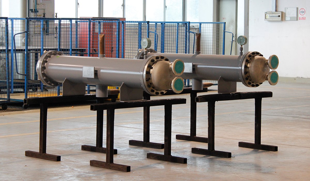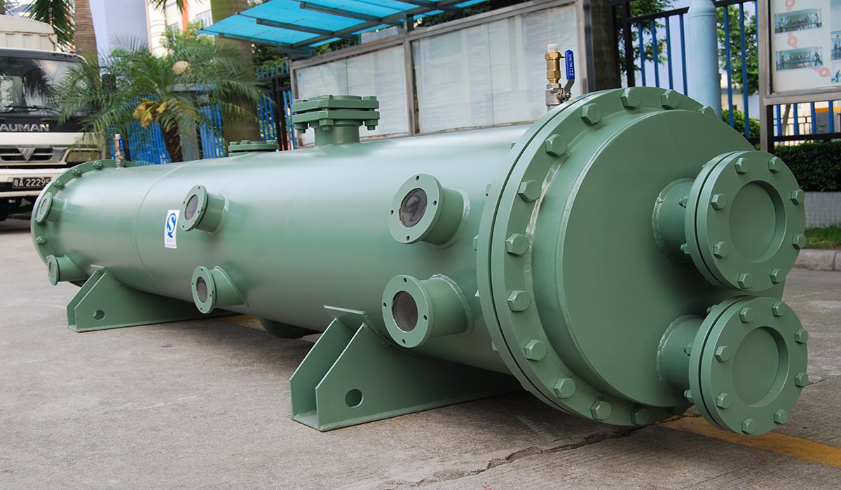
The evaporator absorbs heat from the process fluid and provides the required cooling capacity; because of this characteristic, it is a key component in refrigeration systems.
However, designing an evaporator is not as simple as just matching the cooling capacity.
Evaporator Design Calculation
This section outlines the key data required for evaporator design calculations and guides you through the essential steps.
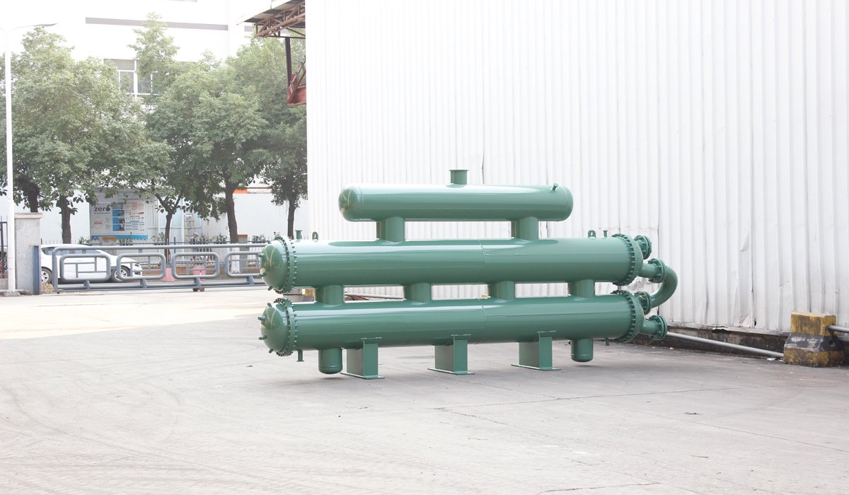
Determining the Required Heat Load
You first need to determine the cooling or heat load your evaporator is handling, as this forms the basis for subsequent design calculations.
Determining the Required Heat Transfer Area
Calculate the heat transfer area needed to meet design specifications based on the thermal load, effective temperature difference, and overall heat transfer coefficient.
Selecting the Appropriate Tube Configuration
After completing the above steps, you need to further confirm your tube diameter, tube length, number of tubes, number of tube passes, and tube bundle arrangement to ensure that the heat exchange performance and flow conditions meet your requirements.
Checking the Allowable Pressure Drop
Finally, it is necessary to check the pressure drop on both the refrigerant and fluid sides to avoid excessive flow resistance affecting system efficiency and normal operation.
What Information Is Needed for Evaporator Design Calculation
Accurate evaporator design calculations require complete operating condition data. The more complete the information you provided, the more accurately the manufacturer can determine the heat exchange area, tube bundle structure, pressure drop, and material selection.
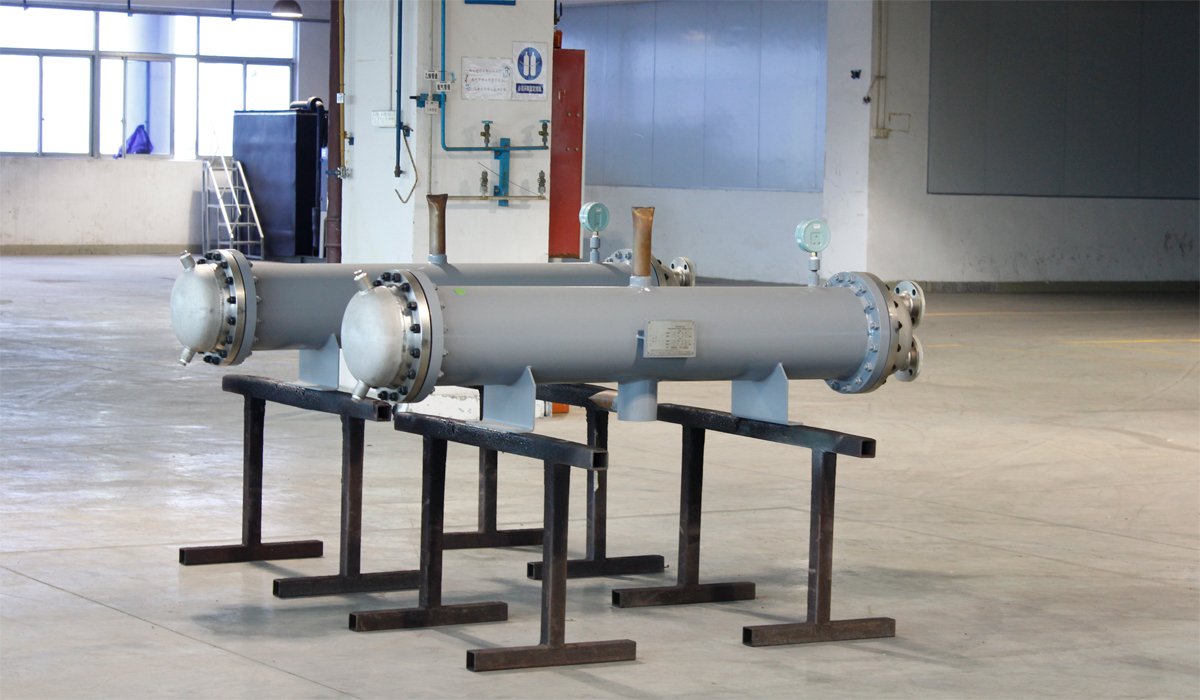
Cooling Capacity Requirement
First, we need to know the cooling capacity, because 100 kW cooling requirement is not enough to define the evaporator design. If we only know that you need “100kW evaporator”, the manufacturer cannot design equipment for you. Therefore, you need to know approximately how much heat the evaporator needs to remove; this is the starting point for the design.
Refrigerant Information
Different refrigerants—such as R134a, R410a, and R407c—have varying pressure, temperature, and heat transfer characteristics, which necessitates different evaporator designs. As you now know,even at the same 100 kW cooling capacity, different refrigerants may require different evaporator designs.
Secondary Fluid Information
This refers to the medium being cooled, typically water, chilled water, glycol, brine, or seawater. You need to specify the inlet and outlet temperatures; for example, “Chilled water 12°C → 7°C” indicates that the evaporator must cool the water from 12°C to 7°C.
Operating Pressure and Temperature
Operating pressure is a critical parameter when designing an evaporator to meet your requirements; this includes refrigerant-side pressure, water-side pressure, and design pressure. Additionally, inlet and outlet temperatures influence the selection of evaporator materials and the design of the pressure vessel.
Material and Corrosion Requirements
Units are used in diverse environments, meaning the evaporator design must be adapted to the specific operating conditions. The corrosiveness of water, seawater, and chemical solutions is different, so when designing a shell-and-tube evaporator, you should also choose tubes made of different materials, such as copper, stainless steel, titanium, or copper-nickel alloy. The shell can also be made of carbon steel or stainless steel. The materials used directly affect the manufacturing cost, lifespan, and reliability of the evaporator.
The table below can be used as a reference:
| Design Parameter | Required Information |
| Cooling capacity | kW / TR |
| Refrigerant | Type and operating condition |
| Evaporation temperature | °C |
| Secondary fluid | Water / glycol / brine |
| Fluid inlet/outlet temperature | °C |
| Flow rate | m³/h |
| Design pressure | bar |
| Material requirement | Copper / SS / Titanium |
| Fouling condition | Fluid cleanliness |
| Installation requirement | Size and connection |
Common Mistakes in Evaporator Design Calculation
Incomplete design parameters
Knowing only the required cooling capacity is not enough. Data such as the refrigerant type, evaporation temperature, flow rate, inlet/outlet temperatures, and pressures are also required.
Liquid-side heat load:
Q = m·Cp·ΔT
Where Q is the heat load, m is the mass flow rate, Cp is the specific heat capacity, and ΔT is the temperature difference between the inlet and outlet.
Simply put, designing an evaporator requires knowing not only “how much cooling is needed” but also “what is being cooled and how.”
Directly applying a fixed U-value
The U-value (overall heat transfer coefficient) is influenced by factors such as the refrigerant, flow velocity, tube material, and fouling. Overestimating the U-value leads to an underestimation of the required heat transfer area.
A = Q / (U·ΔTlm·F)
Where U is the overall heat transfer coefficient.
A common mistake is simply looking up a U-value online and applying it without considering actual operating conditions. In reality, U is affected by factors including the refrigerant, boiling state, flow velocity, tube material, fouling, and flow pattern.
Calculating heat transfer area without checking pressure drop
Sufficient heat transfer area does not guarantee a sound design. Pressure drops on both the refrigerant side and the fluid side must also be checked. For actual shell-and-tube evaporators, one must account for factors such as tube-side passes, inlet/outlet configurations, local resistance, and pressure losses caused by the shell-side flow and baffles.
Excessive pressure drop can affect evaporation pressure, compressor operating efficiency, or water pump energy consumption. Therefore, you also need to be aware that a good evaporator design requires a balance between heat transfer performance and pressure drop.
Equating heat transfer area with final equipment dimensions
For instance, calculating a required heat transfer area of 18 m² does not mean the design is complete simply by selecting an 18 m² evaporator. Parameters such as tube diameter, tube length, number of tubes, number of passes, and shell diameter must be determined. Once the number of tubes is established, one must still verify flow velocity, pressure drop, shell diameter, tube pitch, and manufacturing constraints.
In other words, calculating the heat transfer area is merely the starting point for sizing the evaporator, not the final result. For instance, given an outer tube diameter of Do, a length of L, and N tubes, the theoretical heat transfer area can be approximated as:
A=NπDoL
Therefore:
N=A/πDoL
Example:
A=18m²; Do=0.019m ;L=3m
N=π×0.019×318≈101
Neglecting fouling and refrigerant distribution
Long-term operation can lead to scaling, oil film accumulation, and uneven refrigerant distribution within the evaporator, all of which may reduce actual heat transfer performance.
Therefore, a reliable evaporator design cannot simply stop at calculating the required surface area; you must also verify the heat transfer coefficient, flow velocity, pressure drop, fouling factors, refrigerant distribution, and the final tube bundle configuration.
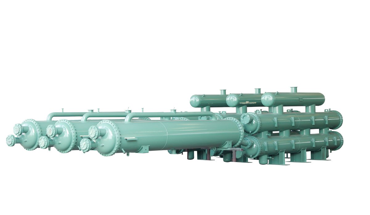
How to Select the Right Shell and Tube Evaporator?
To select a suitable shell-and-tube evaporator, you must first confirm the basic operating conditions such as cooling capacity, refrigerant, evaporation temperature, medium being cooled, inlet and outlet temperatures, and flow rate. Then, you should further check whether the heat exchange area, pressure drop, materials, and structure meet your project requirements.
For different applications, factors such as scaling, corrosion, cleaning, and installation space also need to be considered. Rather than simply comparing heat exchange area or equipment size, it is more important to confirm whether the evaporator matches the actual system operating conditions, and for a manufacturer with design capabilities to conduct the final selection and verification.
FAQ
How do you calculate the cooling capacity of an evaporator?
Q=m˙Cp(Tin−Tout)Where:
- Q = cooling capacity
- ṁ = mass flow rate
- Cp = specific heat
- Tin/Tout = inlet and outlet temperatures
How is the LMTD calculated for an evaporator?
ΔTlm=ln(ΔT1/ΔT2)ΔT1−ΔT2
For a typical evaporator, you use the refrigerant evaporation temperature and the secondary-fluid inlet and outlet temperatures to determine ΔT1 and ΔT2. LMTD represents the effective temperature driving force for heat transfer.
What is the overall heat transfer coefficient (U) in evaporator design?
You can treat U as the overall ability of your evaporator to transfer heat. It combines several thermal resistances:
Main factors:
- Refrigerant-side boiling
- Fluid-side convection
- Tube-wall resistance
- Fouling resistance
A simplified relationship is:
1/U=Ri+Rw+Ro+Rf
You should determine U from your actual refrigerant, fluid, velocity, materials, and fouling conditions rather than using a universal value.
How much heat transfer area margin should an evaporator have?
Margin=ArequiredAselected−Arequired×100%
You should avoid excessive oversizing because it can increase cost and affect flow conditions.
What should you provide when requesting a shell and tube evaporator quotation?
Please provide the cooling capacity, refrigerant type, evaporation temperature, secondary-side fluid, inlet and outlet temperatures, flow rate, operating and design pressures, material requirements, connection details, installation conditions, and applicable standards. Complete operating data helps you calculate the required heat exchange area and provides you with a more accurate evaporator design solution and quotation.
The more complete your data, the more accurately the manufacturer can size and quote your evaporator.
Final Thought
Evaporator design calculations are crucial for ensuring appropriate cooling capacity, heat transfer area, and pressure drop, as well as long-term operational reliability. Tailored to specific project requirements—including your choice of refrigerant, operating conditions, materials, and performance specifications—UAR provides customized shell-and-tube evaporator solutions, helping you transition smoothly from the calculation phase to a reliable final design.