Instruction
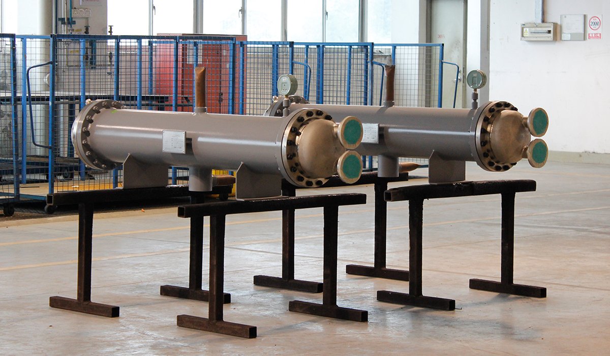
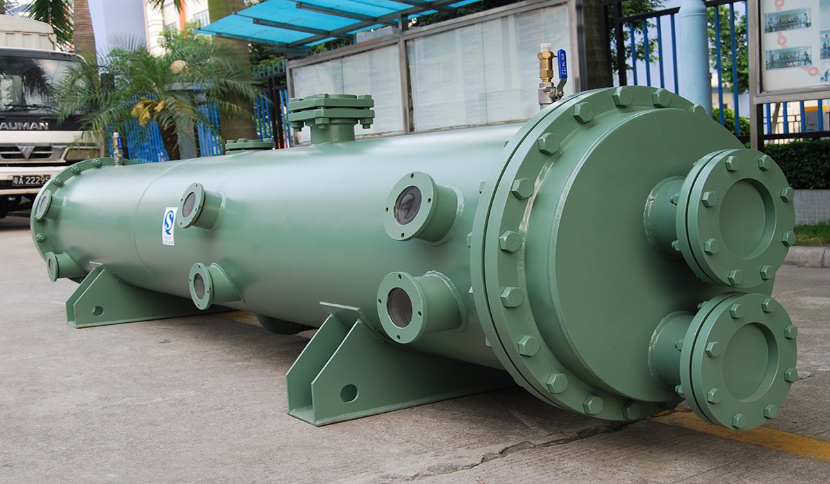
Designing a shell-and-tube heat exchanger involves more than just calculating the required heat transfer area. The final design must strike a balance among thermal load, pressure drop, flow velocity, fouling, material compatibility, mechanical integrity, and maintenance requirements. This guide outlines the considerations for heat exchanger selection and design.
What Is Shell and Tube Heat Exchanger Design?
The design of a shell-and-tube heat exchanger is based on process conditions and operational requirements. We need to determine the heat transfer capacity, fluid flow parameters, structural dimensions, materials, and mechanical design parameters of the heat exchanger in order to design it.
Thermal Design
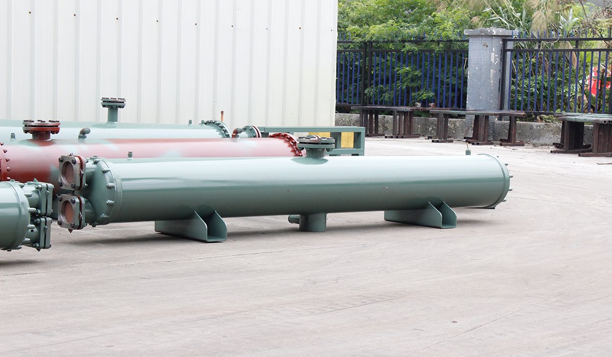
Thermal design aims to verify whether a heat exchanger can meet the specified heat duty and to determine the required heat transfer area. Key factors typically considered include heat duty, inlet and outlet temperatures, flow rate, LMTD, LMTD correction factor, overall heat transfer coefficient, fouling resistance, required heat transfer area, and heat transfer coefficients.
The fundamental relationship can be expressed as:
Q=UAFΔTlm
Where:
- Q = Heat Duty
- U = Overall Heat Transfer Coefficient
- A = Heat Transfer Area
- ΔTlm = Log Mean Temperature Difference
- F = Correction Factor
Hydraulic Design
The main problems to be solved in hydraulic design are how fast the fluid should pass through the heat exchanger and how much pressure loss will be generated by the flow. Shell-side velocity, tube-side velocity, Reynolds number, flow state,tube-side pressure drop and shell-side pressure drop are aspects you need to consider.
If the flow velocity is too low, it may lead to insufficient heat transfer performance and increase the risk of fouling; if the flow rate is too high, it may cause excessive pressure drop and even lead to problems such as erosion and vibration.
Therefore, the goal of hydraulic design is not simply to pursue higher flow velocities, but to find a reasonable balance between heat transfer performance, pressure drop, energy consumption, and equipment reliability.
Mechanical Design
The mechanical design primarily ensures the safe operation of the heat exchanger under specified design pressures and temperatures; particular attention must be paid to the differential thermal expansion between the shell side and the tube side caused by differences in pressure and temperature.
If there is a significant temperature difference between the tube side and the shell side, the tube bundle and the shell may undergo varying degrees of thermal expansion. Improper handling of this differential expansion can result in significant thermal stress.
Therefore, you can select from configurations such as fixed tubesheet, U-tube, or floating head designs to best suit your project.
Material Selection
The choice of materials determines whether a heat exchanger can operate under actual conditions. You must consider factors such as fluid compatibility, corrosion resistance, operating temperature, design pressure, and scaling characteristics, not just price. For instance, when dealing with corrosive fluids, a material’s corrosion resistance may be more critical than its thermal conductivity; similarly, special media like seawater require particular attention to corrosion issues and material compatibility. Therefore, the choice of materials can actually affect heat exchange performance, equipment lifespan, maintenance costs, and even the overall cost of your project.
Simply put, the design of a shell-and-tube heat exchanger involves striking a reasonable balance among thermal performance, fluid dynamics, mechanical integrity, and material compatibility.
How Is a Shell and Tube Heat Exchanger Designed?
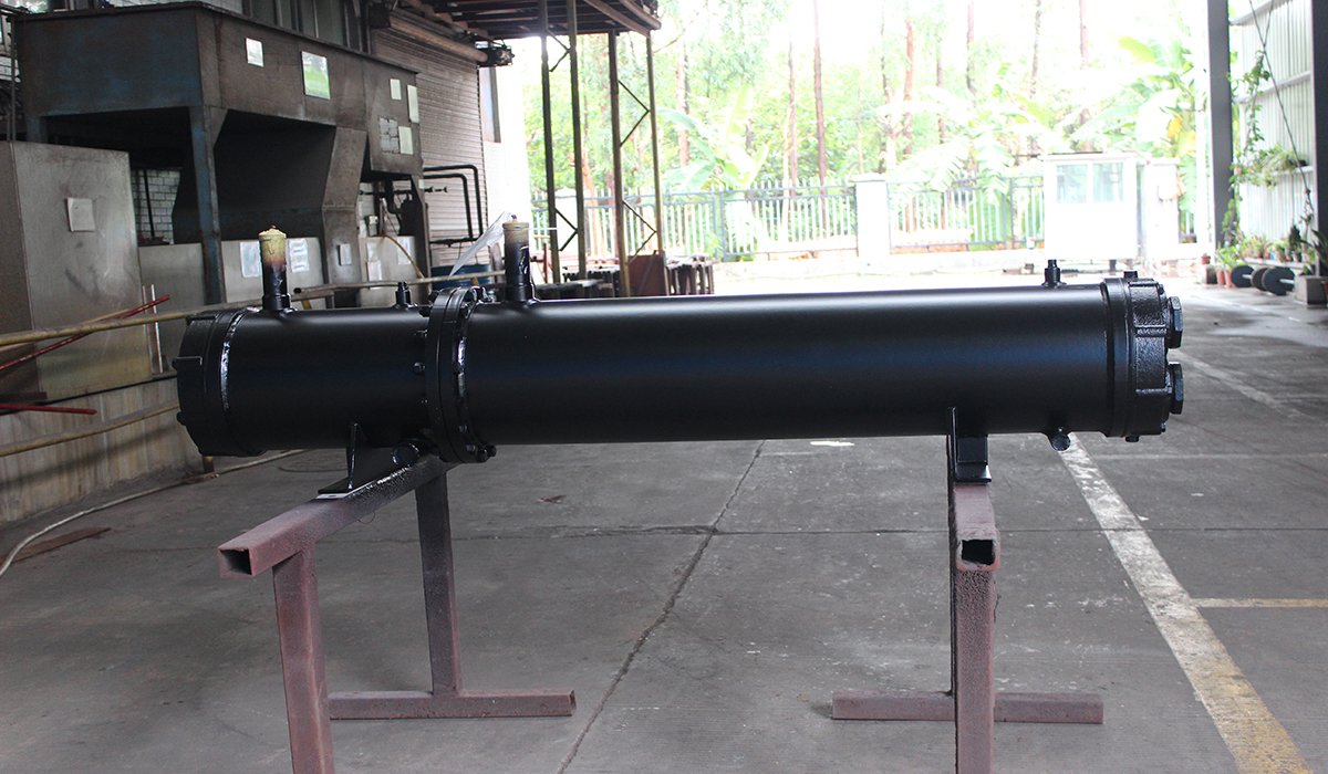
The design of shell-and-tube heat exchangers typically begins with process conditions and heat load, followed by calculation of the logarithmic mean temperature difference (LMTD), estimation of the overall heat transfer coefficient, and determination of the required heat transfer area. Based on this, you further determine the heat exchanger tube size, number of tube passes, number of tubes, shell diameter, and baffle arrangement, and check the pressure drop in the tube and shell sides. Finally, it is necessary to check the material selection, mechanical strength, thermal expansion and vibration to ensure that the heat exchanger meets the requirements of thermal performance, safety and operation.
Here is the design process:
Process Data → Heat Duty → LMTD → Overall Heat Transfer Coefficient
↓
Required Heat Transfer Area → Tube Design → Shell & Baffle Design
↓
Pressure Drop Check → Material Selection → Mechanical Design
↓
Thermal Expansion & Vibration → Final Verification
What Information Is Needed to Design a Shell and Tube Heat Exchanger?
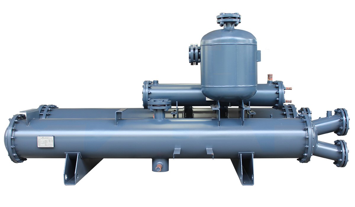
Process Data
Fluid Information
You need to specify the media on both sides of the heat exchanger—such as cooling water, chilled water, refrigerants, steam, oil, or chemical process fluids. Why is this distinction important? Because the choice of medium influences material selection, fouling tendencies, heat transfer coefficients, and flow patterns; furthermore, the operating environment affects the associated risks (such as corrosion or contamination).
Flow Rate
You need to provide both mass flow rate and volumetric flow rate. These parameters directly impact the heat exchanger’s thermal capacity, pipe/tube diameter selection, flow velocity, and pressure drop.
Inlet and Outlet Temperatures
These refer to the inlet and outlet temperatures for both the hot and cold sides. They determine the heat transfer driving force, the Logarithmic Mean Temperature Difference (LMTD), and the required heat transfer area.
Operating Pressure
The operating pressures on the shell side and tube side influence shell thickness, tube wall thickness, tubesheet design, sealing methods, and structural configuration. For instance, high-pressure fluids are typically routed through the tube side because smaller diameters make it easier to withstand pressure and reduce manufacturing costs.
Project Requirements
In addition to process data, actual design must take into account specific project conditions. Different types of heat exchangers—such as evaporators, condensers, and coolers—have distinct application scenarios, and thus the design priorities vary accordingly. Their structural configurations, materials, and design standards must be determined based on the specific project, while requirements for installation and maintenance must also be considered.
| Information Required | Why It Matters |
| Fluid type | Determines material and heat transfer characteristics |
| Flow rate | Determines exchanger size and velocity |
| Inlet/outlet temperature | Determines heat duty and LMTD |
| Pressure | Determines mechanical design |
| Allowable pressure drop | Balances heat transfer and energy consumption |
| Fouling factor | Determines additional thermal resistance |
| Material requirement | Ensures corrosion resistance |
| Design standard | Ensures compliance |
| Installation conditions | Determines final configuration |
Shell and Tube Heat Exchanger Design Example
To understand how you can design a shell and tube heat exchanger, consider a simple water-to-water cooling application. You need to cool 10,000 kg/h of hot water from 90°C to 60°C using 12,000 kg/h of cooling water entering at 25°C and leaving at 40°C. Assume the specific heat capacity of water is 4.18 kJ/(kg·K).
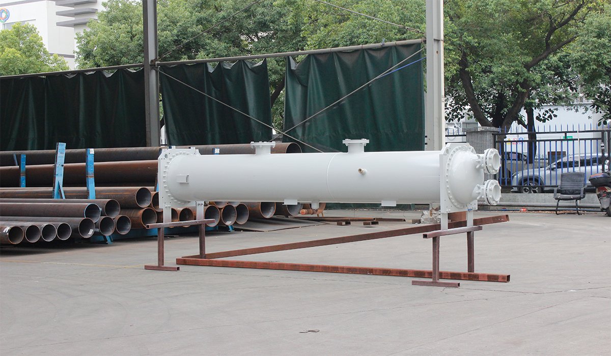
1. Calculate the Heat Duty
You can calculate the heat duty using:
Q=\dot{m}C_p\Delta T
Q=10,000\times4.18\times(90-60)
Q=1,254,000/3600=348.3 kW
So, you need a heat exchanger with a required heat duty of approximately 348 kW.
2. Calculate the LMTD
For counter-current flow:
ΔT1=90−40=50°C
ΔT2=60−25=35°C
ΔTlm=(50−35)/ln(50/35)≈42.1°C
3. Calculate the Required Heat Transfer Area
Assume an overall heat transfer coefficient of 800 W/(m²·K) and an LMTD correction factor of 0.95:
A=Q/UFΔTlm
A=348,300/(800×0.95×42.1)≈10.9m²
You therefore need approximately 10.9 m² of heat transfer area.
4. Select the Tubes
If you select 19 mm OD tubes with a 3 m length, the outside surface area of each tube is:
At=πdoL=π×0.019×3≈0.179 m²
The preliminary tube count is:
N=10.90.179≈61You can then select a practical tube count, such as 64 tubes,Since tube count is also affected by tube-pass arrangement, tube layout, shell diameter, and manufacturing requirements, you can select a practical tube count such as 64 and then recalculate the actual heat transfer area. and continue checking tube-side velocity, shell-side velocity, pressure drop, vibration, material compatibility, and mechanical requirements before finalizing the design.
This example is for preliminary sizing only. Your final shell and tube heat exchanger design should be verified against the actual process conditions and applicable design requirements.
FAQ
What information do you need for shell and tube heat exchanger sizing?
heat duty, flow rate, inlet and outlet temperature, operating pressure, allowable pressure drop, fluid properties and fouling factor.
If you are working with a custom shell and tube heat exchanger project, providing these parameters will help UAR evaluate your preliminary sizing and recommend a suitable configuration.
How do you select the tube diameter and length for a shell and tube heat exchanger?
When you select the tube diameter and length, you need to consider heat transfer area, fluid velocity, pressure drop, fouling, cleaning requirements and available installation space.
For custom shell and tube heat exchangers, UAR can adjust tube diameter, tube length, tube passes and tube count according to your operating
What should you provide when requesting a shell and tube heat exchanger quotation?
When you request a quotation, you should provide the fluid type, flow rate, inlet and outlet temperatures, operating and design pressure, allowable pressure drop, heat duty, material requirements and applicable standards.
The more complete your process data is, the more accurately UAR can evaluate the required heat transfer area, configuration and overall specifications for your project.
If some parameters are unavailable, you can still provide the information you have and discuss the remaining requirements with UAR’s engineering team.
Final Thought
Designing a shell and tube heat exchanger is about more than calculating heat transfer area. You need to balance thermal performance, pressure drop, materials, mechanical integrity, and long-term reliability. With your process data and operating requirements, UAR can help you develop a customized shell and tube heat exchanger designed for your specific project needs.